All posts by Jeff

IC Shroud Test – Cleaned Up Data

Following up on the initial results that were recorded to assess the mass air flow through a portion of the intercooler core.  The raw data included various speed changes and spanned several minutes worth of driving, both of which made comparing the different configuration results challenging.

Chart of shrouding maf test
Shrouding MAF Test


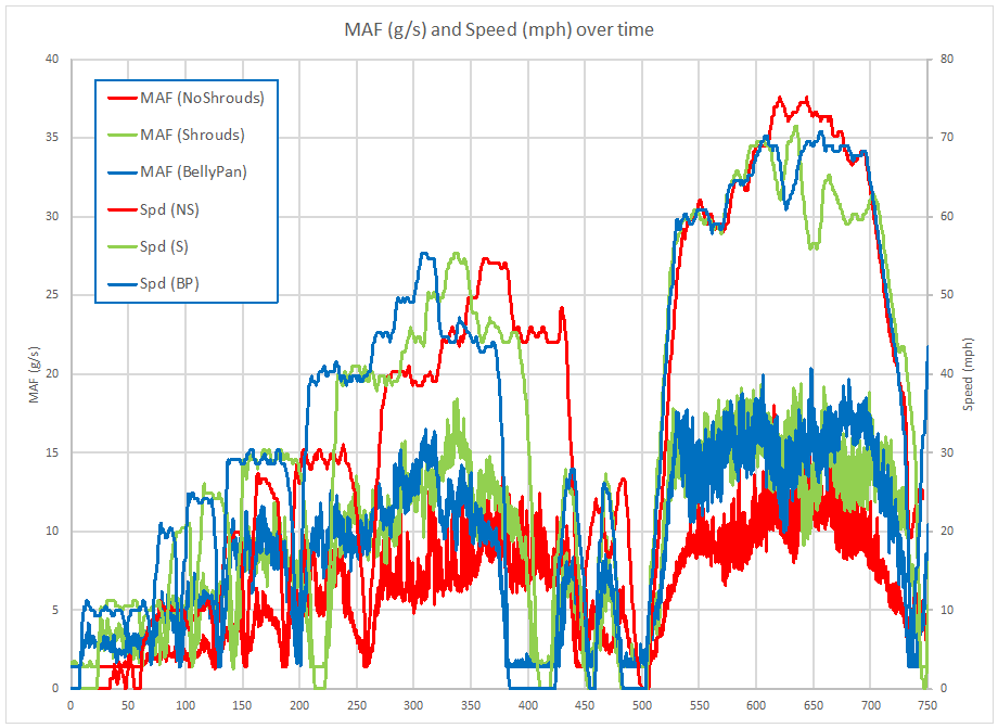
Presented below is data that has been sifted through to extract specific conditions so as to allow a direct comparison of like cases.

For each speed I found the median value for the time period that the speed was being held, and for the accompanying MAF readings I also found the median value.  These are presented on the chart as discrete points and then connected by lines to help with illustrating the trend.

It can bee seen that there is some variances in speed between the different conditions, i.e. one case may have a median speed of 39.8 mph while a comparison case has a median value of 40.4 mph.  Holding the exact same speed on the road at different times would be hard achieve and I believe the results are close enough to represent the underlying truth values.

Chart of intercooler shroud comparison data

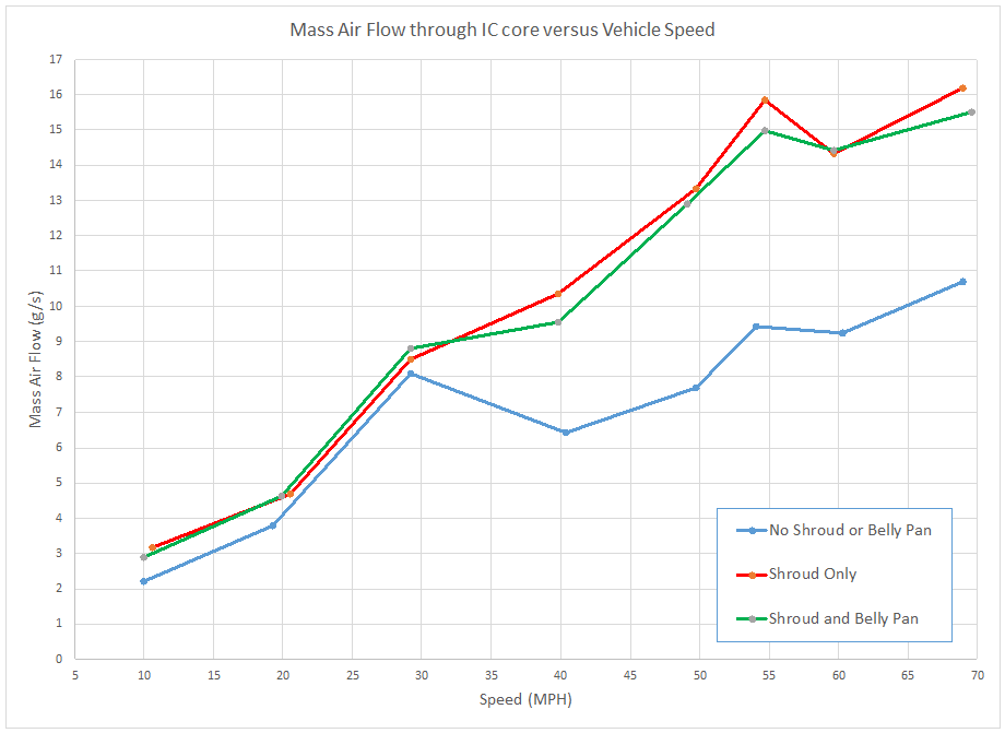
The chart illustrates a couple of interesting points.

  1. That the addition of the shrouds improves the mass airflow through the section of the core that the MAF is located behind.
  2. Going from 30 to 40 mph for the case without shrouds shows a drop in mass air flow.  (Air flow into the area forward of the IC core or pressure behind the core is likely being disrupted by some interaction with another part of the vehicle.)
  3. Even at 50 mph the case without shrouds has not recovered to the air flow rate recorded at 30 mph.
  4. All test cases show a drop in air flow going from 55 to 60 mph.  (This is likely another secondary interaction that is impacting the air flowing through the core.)
  5. All three cases show roughly the same increase in air flow through the core versus speed increase.  If the 30-40 mph drop in the case of the “No Shrouds” had not occurred the rate of increase in mass air flow rate would have mirrored the other two cases closely.
  6. Above 30 mph the absence of the belly pan appears to have improved airflow through the IC core.

Conclusion:

These results show a clear benefit to having the shrouds installed for increasing mass air flow through the section of the intercooler core where the MAF sensor and housing were placed.

The results don’t give any indication as to the affect of mass air flow rate on intercooler performance, and subsequently the charge air intake temperature.  It is possible that a mass air flow rate of 5 g/s is adequate to transfer away the maximum amount of heat available across the core fins and that additional air flow in excess of that amount is unusable, therefore not decreasing the intake air temperature any further.

TTE550 Day 2

Today I tried to make more progress on removing the studs from the turbine housing of the TTE550 turbochargers that I received yesterday.  I picked up a stud removal tool to help with my extraction attempts of the stuck stud.

I also had left penetrating oil on the studs for the past 24 hours.  I started off with trying to loosen the studs on the second turbo as I let the corner of the turbine housing with the pesky stud be blasted by a heat gun for several minutes.

To my pleasant surprise I was able to remove the studs from the second turbo with my fingers.  Four down, four to go.

I went back to the first turbo and attached the stud removal tool.  With the help of a breaker bar the stud slowly began to loosen.  With the pesky stud out I had hopes that the other three would be easier, but that was not to be.  I repeated the heating process on the second stud, and again with a great deal of force I was able to slowly extract the stud.  Then my luck ran out.

I heated the third corner and attached the stud removal tool.  Part way through my initial pull the stud gave out and sheared off about halfway down the stud.  There was still enough thread left to get a good bite on the stud with the removal tool, so I attached it again and tried some more.  Again the stud sheared, this time inside the turbine housing.  Lovely.

The last one was a repeat of the third, the stud sheared halfway down and I threw in the towel at that point not wishing to have two studs broken off inside the turbine housing.

WTF is going on here.  My best guess is that these studs were never taken out at TTE.  The turbine housings were purchased from TTE as they were known to be good used units with no cracks in them.  I was having a set of K04’s upgraded and the original turbine housings were deemed unacceptable for use in the upgrade.   Apparently they never tried taking the studs out of these used housings before working on the housing and sending the completed product to me.

Here’s what I’ve got now:

Picture of TTE550 Turbine Stud Carnage
TTE550 Turbine Stud Carnage

I was hoping to avoid taking the turbo to a machine shop, but drilling out the studs is not something I’ve got the tools for, so it looks like I’ll be researching a place to get me out of this jam.


TTE550 First Look

A set of TTE550’s has arrived for evaluation.  The turbochargers came well packed and even included a balance sheet for each turbo, a nice addition for turbo’s that have been rebuilt to upgrade the BorgWarner K04’s to a hybrid using a variant on the RS6 center.

pair of tte 550 turbochargers
TTE550 RS4 K04 Hybrid Turbochargers


Looking them over it dawned on me that the ring that goes around the wastegate canister increases the effective diameter of the canister, and I have encountered problems fitting the TiAL turbo inlets past the BW K04 wastegate canisters.  This could lead to future headaches when I start installing these turbo’s.  The ring can be loosened and rotated, hopefully that will be enough to avoid problems fitting them alongside the inlets

tte 500 turbocharger compressor housing


I next turned my attention to giving the TTE550 a turn on the flow bench, something I have done with the BorgWarner K03 and K04 products in the past.  First though I’d have to remove the turbine housing studs so I could fit the turbine housing flush to the flow bench.

tte 550 turbocharger turbine housing


I’ll just twist this first stud out, or maybe not.  Vice grips, nope.  Penetrant oil & heat, nope.  F*******ck.  Not coming out.  Looks like I’ll be making a trip to a machine shop to have the studs removed.

TTE 550 turbo stuck stud


Until that takes place I won’t be making any progress with further evaluating these TTE550 turbocharger’s.

To be continued…