All posts by Jeff

Path Temperatures Along Intake Tract

Currently I have air temperature sensors located at various points along my S4’s intake path to monitor the air temperature under various driving conditions.

There is one sensor located in the intake pipe leading into the turbocharger compressor, approximately 10 inches before the inlet.

Another sensor is located in the hard pipe at the turbocharger compressor outlet but before the air to air intercooler.

I have access to temperature data from the vehicle intake air temperature sensor which is located at the entrance to the intake manifold.

A fourth air temperature sensor is the vehicle outside air temperature sensor located in front of the radiator.

Driving while logging these locations provides some idea of how the different components affects the temperature of the intake air as it travels along it’s path to the engine.

Shown below is a chart of these temperatures over several minutes of driving under changing conditions.

Chart of intake air path temperatures

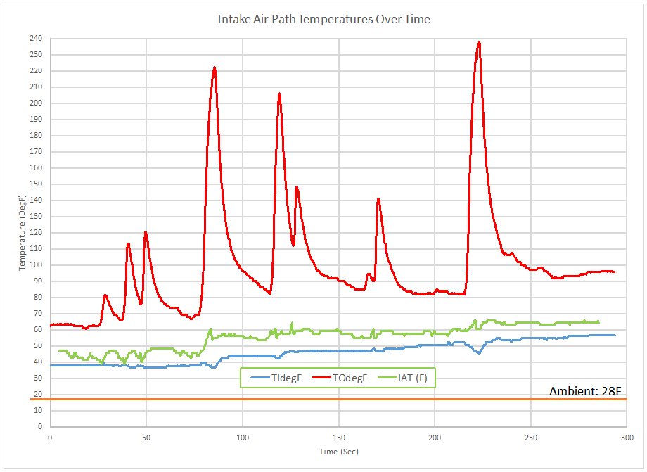
As documented on the chart, the orange line was the atmospheric temperature at the time of this drive, a cold 28 degrees Fahrenheit.

The blue line shows the temperature of that air after passing through the intake snorkel, airbox/filter, MAF housing, accordion, Y-pipe, and upper turbo inlet piping.

Note: This log was made after driving for a short while, prior to which the vehicle was parked inside a garage where the air temperature was around 50 degF.

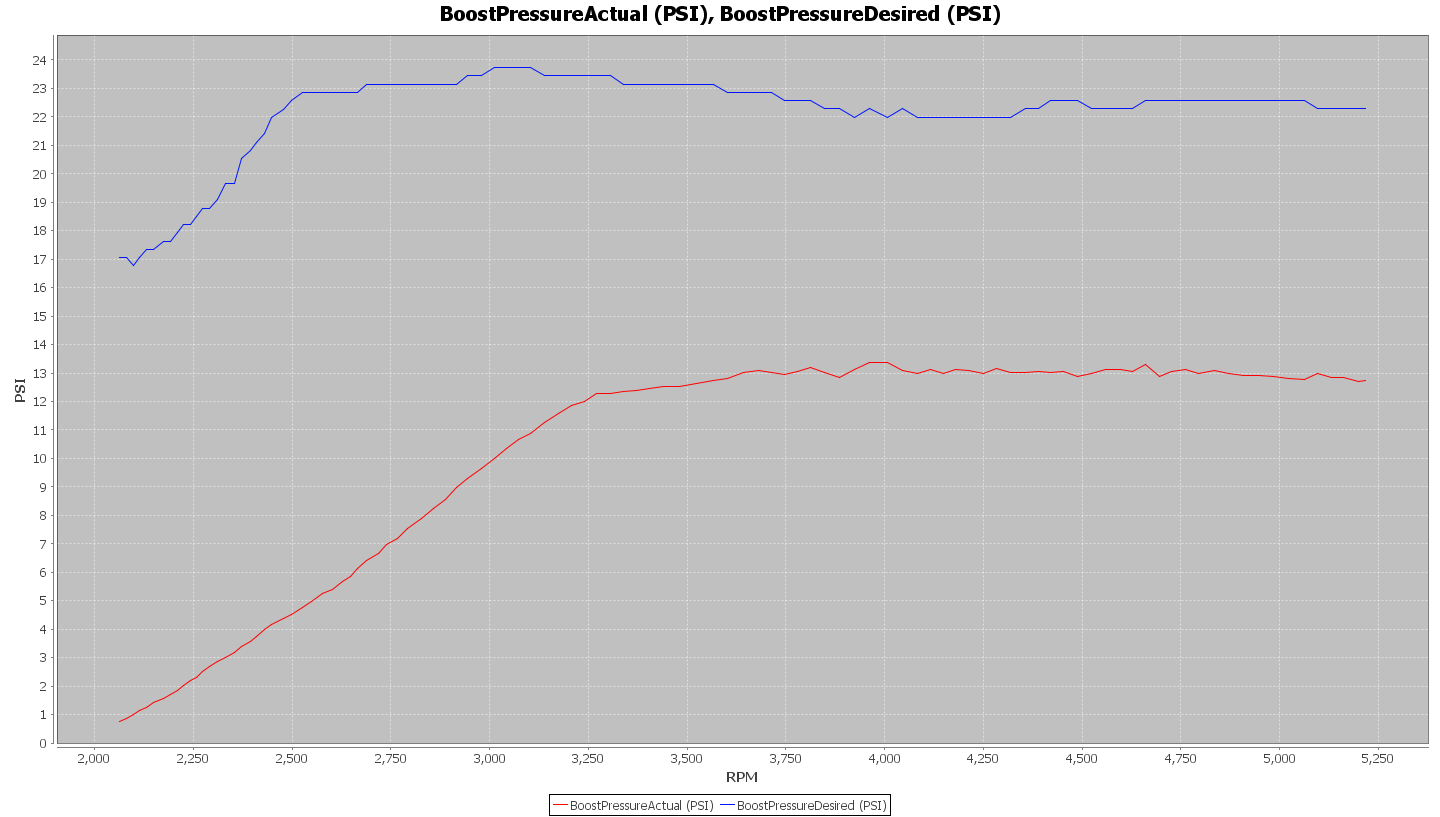
The red line shows the next stop on the air’s journey to the engine, after it has passed through the turbocharger compressor.  The large upward spikes indicate when the turbochargers were producing boost, around 22 psi in the case of the larger spikes.

Last, the green line shows the temperature after the air has passed through the intercooler and is entering the intake manifold.

Observations:

One of the most obvious take-aways from this chart is how substantially the turbochargers heat the intake air when producing boost, even at relatively modest levels for a stage 3 setup.

Another significant point is how well the intercoolers work at bringing that temperature back down so what is fed to the engine is relatively cool.  During this drive I was using the Silly Rabbit Motorsport B5 S4 SMIC’s.

Something this chart does not answer, but may provide some perspective about, is the significance of additional methods at heat management.  For example, thermal wraps, reflective barriers, cold air intakes, etc.  If the turbocharger is raising the temperature of the air up to 200 degF above the temperature it enters the compressor at, and then the intercooler pulls that air temperature back down by about 190 degF, is wrapping the entire intake path going to make much difference in the outcome?

Fluidampr crankshaft pulley

Soon to be installed on my S4 is one of the Fluidampr engine dampers.

Fluidampr 2.7T engine dmapener

I’m not expecting to be able to detect any difference from the driver’s seat, but hopefully it will help with engine longevity, especially at higher than stock horsepower levels which I expect my car to be operating at.

Here’s it is on a bathroom scale, weighing in at 7.2 lbs.

fluidampr_weight

And a couple more angles of the product.

fluidampr_bottom

fluidampr_side

Today I removed the stock crankshaft pulley and weighed it on the same scale to compare with the Fluidampr weight.

stock_damper_weight

  • Stock: 4.6 lbs
  • Fluidampr: 7.2 lbs

Here’s the two parts side-by-side:

fluidampr_stock_damper
(L-R) Stock, Fluidampr

Installed on the S4.

fluidampr_installed_27t

Finally, some additional information about what these viscous dampers do to help mitigate the affects of torsional vibration.

F21 First Logs

After puzzling over the results I was getting yesterday (shown directly below) I began thinking about what I could have done during the turbocharger swapping that may have messed with the F21 wastegates.  The tune was ruled out after conferring with Daz, (who is helping with my tuning efforts), that this initial tune should have been similar to the K04 boost profile and had a low wastegate duty cycle.

f21mf_boost

Preload checks were good after installing the engine.

The one other change I had made was to solder a wire to the N75 to enable the boost cutoff safety that the TorqByte WMI controller uses.  The perplexing part was that I hadn’t completed the wiring, I’d simply spliced into the wire going to the N75 and left the rest of the wire coiled on it’s spool and tucked under the Y-pipe.  Without anything else changing I decided to look at this wire as a possible cause of the problem.  Sure enough, when checking the continuity on the N75 connector it was getting a good check with the ground terminal on the battery – that shouldn’t be happening.  Upon closer inspection I found that the end of the wire inside the spool was bare and had managed to come into contact with the top of the intake manifold.  I wrapped the end in electrical tape and the problem went away.  Out for a check with the N75 disconnected, proving that the wastegates were functioning correctly and limiting boost to 13-14 psi.

N75 electrically disconnected

Then I reconnected the N75 valve and made a few abbreviated pulls starting at different engine speeds to assess how the boost onset looked.

Chart of FrankenTurbo Mixed Flow F21 Boost Onset
FrankenTurbo Mixed Flow F21 Boost Onset

In a follow up I’ll be comparing these results with similar data from the BorgWarner K04’s.

I have discovered that I have oil dripping from the driver side turbocharger – doh!  I was hoping that it may have been coming from the oil return line, but after checking I found those bolts to be tight so I am now left with trying to check the oil supply line, which will entail taking the engine back out.