There are a few bits of interesting data that I’ve recorded while measuring boost pressure for fixed wastegate duty cycles. This is part of my effort to fine tune the KFLDRL numbers for the new wastegates that the TTE550’s use.
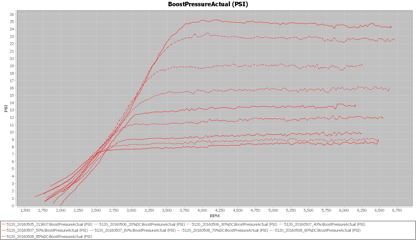
Each fixed wastegate duty cycle produces a different boost level. The range of boost levels that were recorded in third gear are shown below. Note: The recording in third at 10% was not long enough to make including the results worthwhile.
Boost Level for Fixed WG DC (TTE550 turbochargers)
The chart above shows fixed WGDC’s of: 0%, 20%, 30%, 40%, 50%, 60%, 70%, 80%, and 85%.
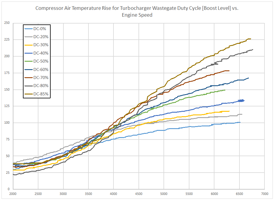
For each of these boost levels I also recorded the air temperature going into the turbocharger compressor, along with the temperature after exiting the compressor. The approximate rise in temperature caused by the compression of the air for each boost level is shown below.
Air Temperature Rise (degF) for Boost Levels
Note: This is an approximate rise due to the location of the air temperature sensor being slightly downstream from the turbocharger compressor outlet. The air temperature exiting the turbocharger is likely higher than what is recorded due to cooling taking place in the charge pipe prior to the air passing over the temperature sensor.
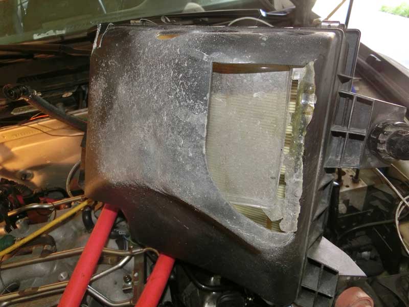
This is an example of why I have tried to keep the added openings on my stock airbox on the forward facing side and have retrofitted a baffle on the lower opening I created.
Dirty Bottom Airbox
After driving in some rainy conditions the dirty water from the road has coated the bottom of the airbox. If this area was more open it would be possible for the water to coat the air filter instead.
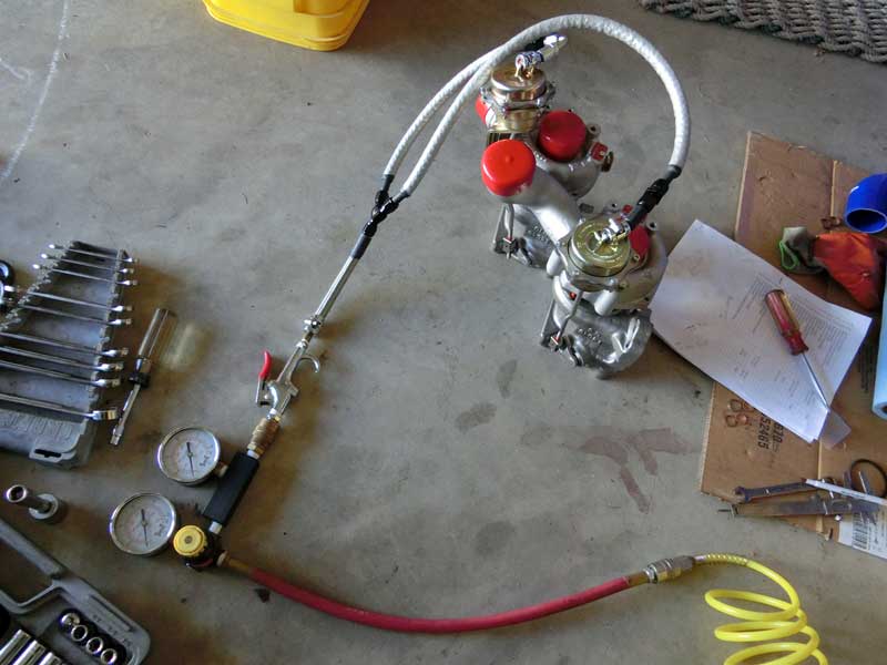
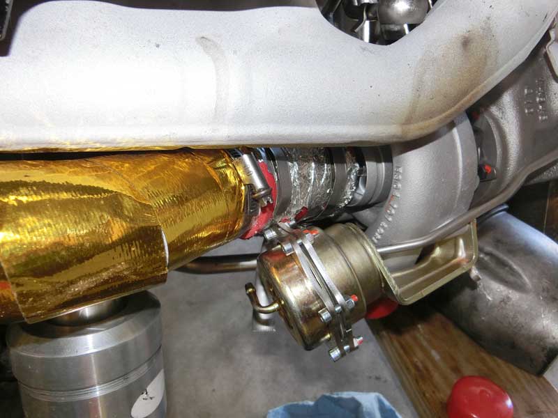
Today I began installing the TTE550 turbochargers onto the engine. Step number one was to check the wastegate preload to confirm the 0.55 bar that I was told they were set to prior to delivery. The setup shown below is what I use for checking the preload.
Wastegate preload check
The yellow hose runs from an air compressor tank, through a pressure regulator (that I purchased for performing leak down checks on the engine cylinders), and then via an AN Y to a pair of hoses that connect to the wastegate canisters. As the regulator is slowly opened I monitor for movement from the wastegate arms, and when movement is seen I’ll check the pressure. This is repeated a few times to get confidence that each wastegate is beginning to open at the same pressure.
As it turned out the preload was set to only 5 psi. With intentions of running around 24-25 psi out to 7000 rpm I was not confident that would be enough preload on the wastegates. I increased the preload on both wastegates to 8 psi.
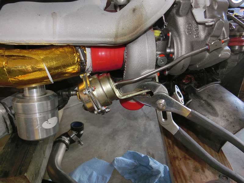
An issue I expected to encounter was with the wastegate canister interfering with the turbo inlet pipe.
Inlet and wastegate interference
TTE adds a pair of rings around the wastegate canister that is concave in between the fasteners. At the mid-point between the bolts the ring is about flush with the lip around the wastegate canister so that it isn’t any wider than the wastegate canister by itelf. But where the bolts are located it is taller, and as luck would have it that was where the inlet pipe came closest to the wastegate canister.
I loosened the bolts and rotated the rings slightly and gained some clearance, but there was still some contact between the two parts. As I’ve had to do in the past, I took a set of pliers and bent the wastegate bracket down slightly to gain some additional clearance. This produced enough of a gap that I felt good about the setup.
Clearance gained
Of course by slightly altering the location of the canister I became concerned that I might have also affected the amount of preload on the wastegate, thereby possibly causing the wastegates to open at slightly different pressures. So I hooked the wastegates back up to the preload checker and confirmed that the tweaking had not altered the preload in any meaningful way.
I use a silicone coupler to attach the turbo inlet pipe to the turbocharger compressor intake. Something I wanted to make sure not to do was disturb the airflow going into the compressor by creating a gap between the edge of the coupler and the outer lip of the compressor inlet.
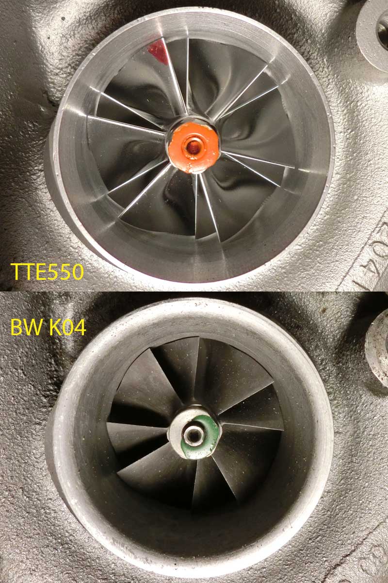
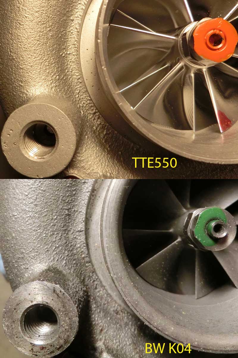
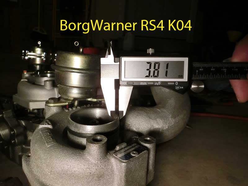
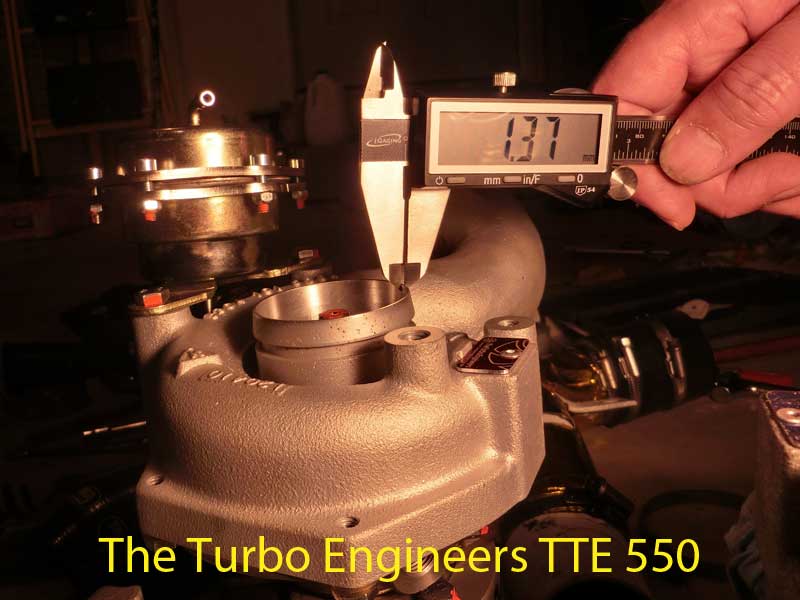
TTE goes to some effort to port the inlet from what a standard BorgWarner RS4 K04 looks like, as shown by the comparison photographs below:
Inlet lip comparisonInlet lip comparison – close up
And the TTE lip is measurably thinner than that of the standard K04.
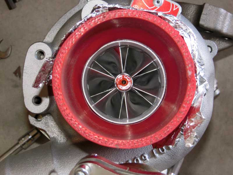
To ensure that I was not creating more turbulence than will occur anyhow I was careful about where I placed the clamp that holds the silicone coupler to the compressor inlet.
Silicone coupler attached to compressor inlet
The intent being to minimize the gap between the silicone and inlet.
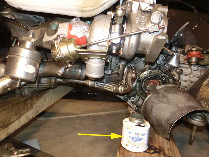
Another lesson from the last turbocharger swap is not to trust the crush washers. With the FT21’s I ended up with a washer on the oil supply side to the turbocharger dripping oil, leading to an unplanned engine pull to fix the drip.
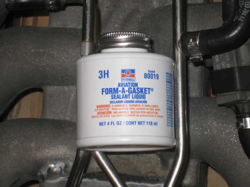
To address that possibility I am attaching a gasket forming material to each side of the crush washers that are used on the oil supply, coolant supply, and coolant return banjo bolts.
Sealant
My hope is that this extra step will all but eliminate the chance of a leak from these lines.