All posts by Jeff

More TTE550 Boost Onset Data

Taking advantage of some unseasonably cool weather I had the opportunity to record the boost onset characteristics of the TTE550 turbochargers under conditions more like those when the BW K04’s (and FT21’s) were logged.

Shown below is the 2-11 time for the BW K04’s and TTE550’s.  The 2-11 time represents how much time passes during boost buildup from when pressure reaches 2 psi and then builds to 11 psi.  This measurement is made beginning at a variety of engine speeds typical of my normal driving state.

Chart of BW K04 vs TTE550 2-11 time
BW K04 vs TTE550 2-11 time

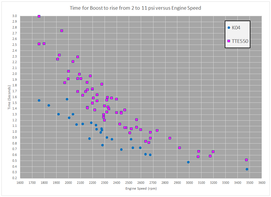
While the TTE550 clearly trails the BW K04s at all engine speeds the difference becomes less pronounced with increasing engine speed.

Ambient temperature does come into play when measuring boost onset.  The chart below illustrates the response from the TTE550 under different ambient temperature conditions.

Chart of TTE550 2-11 time with ambient temperature represented
2-11 time with ambient temperature represented

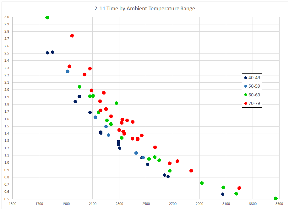
The various measurements are grouped in range categories (degrees F) to make the presentation clearer.

This does obscure the fact that some of the differences in ambient temperature may be minor, or significant.  For example, a reading can be made at 48 degF and compared with another at 50 degF that resides in a different category despite there only being a 2 degF difference.  Also, within the same category one reading could be made at 50 degF and another at 59 degF.

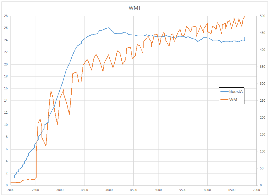
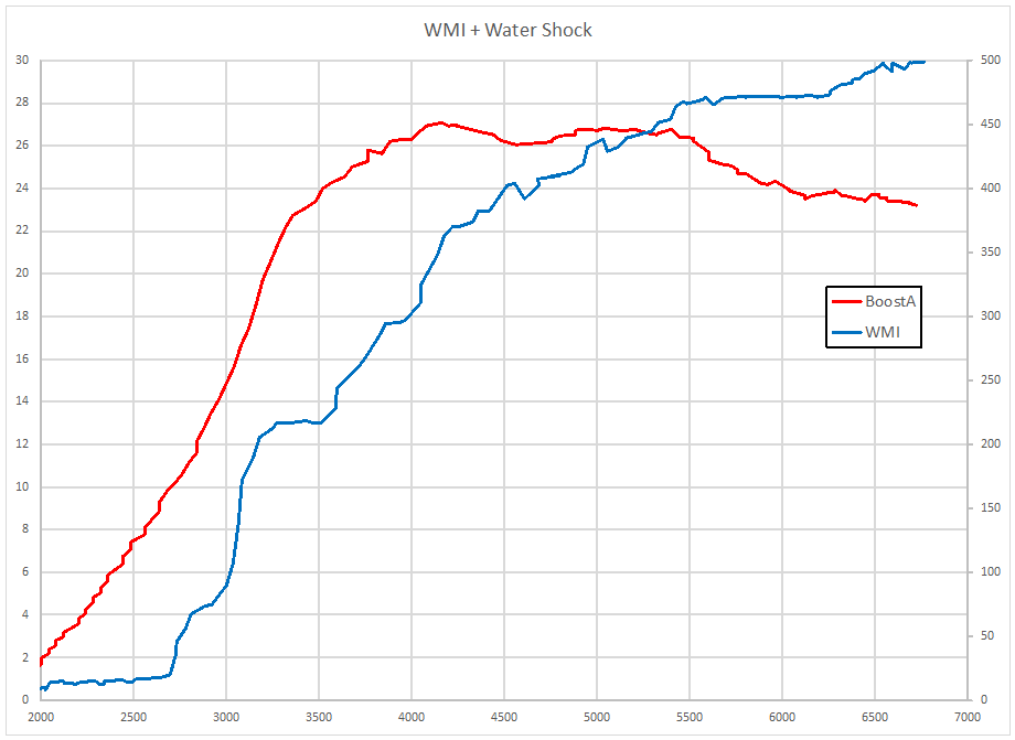
Looking at this boost onset in a more familiar form, I have charted the boost onset at various starting engine speeds against engine speed.  This chart was made from measurements taken at an ambient temperature of 41 degF.

Chart of TTE550 Boost Onset
TTE550 Boost Onset

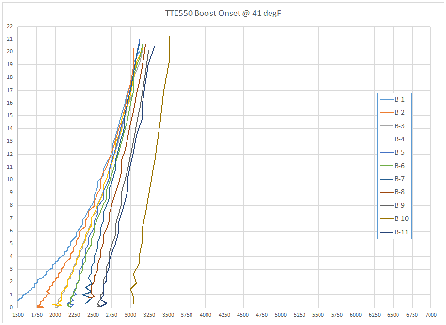
Impressively, at lower engine speeds the TTE550 is reaching approximately 17.5 psi at 3000 rpm.

Revised Water Shock Accumulator

Prompted by a suggestion that a different orientation of the water shock / anti-surge accumulator would be better for this setup I took the time to rearrange the hoses for the accumulator and the nozzle supply.

Aquamist Water shock accumulator

The new orientation of the accumulator off of the tee has the fluid exiting the pump proceeding directly toward the accumulator, and then veering off 90 degrees to go to the nozzles.

A log with this new orientation is shown below:

wmi_accumulator_straight_shot

Overlaying the two accumulator orientations leads to the chart below:

wmi_accumulator_overlay

The difference around 3000 rpm is almost certain to be related to the manner in which boost built during the two sessions, rather than a result of the different orientation.

It is hard to discern if there has been any change to the quality characteristics of the flow with the change to the placement of the anti-surge accumulator; but there has not been any detrimental effects from the change so I plan to leave the accumulator in the new location.

Water Shock Results

Results from installing the Aquamist water shock (aka anti-surge accumulator) are shown below.  The charts are labeled with the boost pressure, psi, along the left vertical axis, and the water-methanol injection flow rate, mL/min, on the right vertical axis.

Water shock installed


Prior to install – no accumulator inline:

WMI without accumulator

After installing the accumulator:

wmi_plus_water_shock

The boost profile was different for each hardware configuration, and I also altered the TorqByte WMI pump duty cycle table, thus the flow rate is not expected to be the same for each of these cases.  What I was looking for was to see what effect the anti-surge accumulator produced.

I was hoping that it would serve to smooth out the injection flow rate, which it has done.  The oscillating flow rate in the first chart has become much more steady in the second chart.  It looks like figuring out how to permanently include the accumulator in the setup will be the next order of business.